Band-Stop Filters: Cutoff Frequencies, RLC Circuits and Notch Applications
- Published
- Author
- Komal Ganvir
- Reads
- 982
Band-stop filters pass frequencies outside a selected range. RLC and Twin-T designs target broad bands or narrow interference such as 50 Hz and 60 Hz hum.
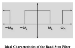
A band-stop filter removes or attenuates signals across a chosen frequency range while passing frequencies on either side. That two-passband, one-stopband response makes it useful when an unwanted component sits between signals a system needs to retain. The design may combine low-pass and high-pass sections, use an RLC network, or target a single frequency with a notch filter.
Two cutoffs define the rejected band
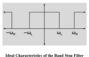
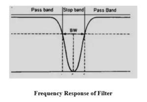
The lower cutoff frequency, fL, and upper cutoff frequency, fH, mark the edges of the stopband. Frequencies below fL and above fH fall in the passbands; frequencies between the cutoffs are attenuated. Component values and circuit configuration determine where those boundaries lie.
An ideal response would reject every frequency inside the stopband completely and pass everything outside it without loss. Real circuits have gradual transitions, and their attenuation and response shape depend on the design and components. The useful engineering question is therefore how much rejection is needed across which range, and how much change to the wanted signals the application can tolerate.
Combining low-pass and high-pass paths
One way to produce a band-stop response is to place a low-pass filter and a high-pass filter in parallel, then combine their outputs appropriately. The low-pass path carries lower frequencies; the high-pass path carries higher frequencies. In the intervening range, the combined circuit attenuates the signal.
The result is the inverse pattern of a band-pass response: the band-pass filter passes a middle range and attenuates frequencies on either side, while the band-stop filter passes the lower and upper ranges and suppresses the middle. The response depends on how the sections are connected and on the values chosen for their components.
RLC circuits shape the rejection
Resistors, inductors and capacitors can also form a band-stop filter. Their frequency-dependent reactance lets the circuit respond selectively: at low frequencies, an inductor has low reactance and a capacitor has high reactance; at high frequencies, those relationships reverse. Near resonance, the inductor and capacitor create a strong frequency-selective response. Whether that response produces rejection depends on how the components are connected.
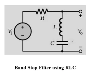
In an RLC band-stop circuit, the component arrangement produces attenuation around the selected frequency range, while frequencies outside that range pass with comparatively less attenuation. The resistor controls damping and the filter’s quality factor. The resistor, inductor and capacitor values, together with the circuit configuration, set the lower and upper cutoffs and influence the shape of the rejection band.
That means component selection is tied to the desired response: the circuit must suppress the unwanted frequencies while preserving the signals outside the stopband as required by the system.
A notch filter targets a narrow range
A notch filter is a band-stop filter designed to reject a narrow range around a centre frequency. It is useful when interference is concentrated near one frequency, such as power-line hum at 50 Hz or 60 Hz in audio and electronic equipment.
A common implementation is the Twin-T notch filter. It uses two T-shaped networks in parallel: one resistive-capacitive network and another network combining resistors with a capacitor arrangement. For a balanced Twin-T circuit, the centre frequency is:
fC = 1 / (2πRC)
- fC: Centre, or notch, frequency in hertz (Hz).
- R: Resistance in ohms (Ω).
- C: Capacitance in farads (F).
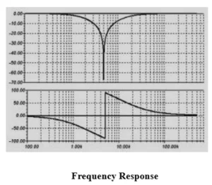
Selecting R and C sets the notch frequency within the chosen circuit configuration. The frequency response has a deep attenuation point at the centre, with nearby frequencies reduced and those beyond the narrow stopband allowed through.
Where band-stop filtering is used
Audio equipment uses these filters to reduce hum and other unwanted components. Applications include electric guitar amplifiers and public address systems, where selected interference can degrade sound or contribute to feedback. A notch response can address a specific hum frequency; a wider stopband can suppress a broader range of unwanted sound.
In biomedical instruments, notch filters can reduce power-line interference in electrocardiogram (ECG) recordings, helping preserve the measured signal. Image and signal processing systems use band-stop filtering to reduce periodic noise and unwanted frequency components. Radio receivers and other communication systems apply it to suppress interference in a selected range. In DSL systems, it can help reduce interference between frequency bands. Removing selected noise and harmonics can also help limit signal distortion and data transmission errors.
Frequency-selective filtering also has optical applications. In Raman spectroscopy, an optical notch filter suppresses intense laser light so weaker Raman signals are easier to detect. The underlying aim is similar across these uses: reject a defined unwanted component while retaining the signal content the system needs.
For a design choice, the key distinction is bandwidth. A general band-stop circuit attenuates a range between fL and fH; a notch filter concentrates rejection around one centre frequency. The application and the required passband response determine which approach fits.