Butterworth Filters: Flat Passbands, Roll-Off and Implementation Choices
- Published
- Author
- Komal Ganvir
- Reads
- 745
Butterworth filters trade a ripple-free passband for a wider transition band, with analog and digital implementations suited to different design needs.
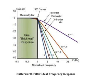
A Butterworth filter is a practical choice when a signal’s passband should remain smooth and ripple-free. Its defining trade-off is straightforward: the response stays maximally flat in the passband, but its transition to the stopband is wider than that of some alternatives, including Chebyshev filters. The design fits applications where predictable passband behavior matters more than a particularly sharp cutoff.
British physicist and engineer Stephen Butterworth described the filter in his 1930 paper, “On the Theory of Filter Amplifiers.” The response can be realized as a low-pass, high-pass, band-pass or band-stop filter, in analog circuitry or digital signal processing. The choice of form and implementation depends on which frequencies need to pass, which need attenuation, and what circuit or processing constraints apply.
What the response tells a designer
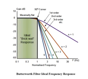
For a normalized low-pass Butterworth filter, the cutoff frequency is the point where output power falls to half its passband value. That corresponds to an output magnitude of about 0.707 times the maximum passband magnitude, or approximately −3 dB. The cutoff therefore marks a defined point in a gradual response; it is not a brick-wall boundary between passed and rejected frequencies.
The squared magnitude response of an nth-order low-pass Butterworth filter is:
|H(jω)|² = H₀² / [1 + (ω/ωc)²ⁿ]
Here, n is the filter order, H₀ is the maximum passband gain, ω is angular frequency in radians per second, and ωc is the cutoff angular frequency. At ω = ωc, the denominator is 2, so the squared magnitude is half its passband value and the magnitude is approximately 0.707 of the passband level.
Increasing the order makes the transition steeper. The asymptotic stopband roll-off is approximately 20n dB per decade: a first-order filter falls at about 20 dB per decade, or approximately 6 dB per octave. Higher order can improve rejection beyond the cutoff, but it does not remove the basic trade-off: the Butterworth response remains less abrupt through the transition band than some ripple-based designs.
From response to circuit
The transfer function describes how the output relates to the input. In voltage terms, H(jω) = Vout / Vin, where Vout is output voltage and Vin is input voltage. The frequency variable is ω = 2πf, with f in hertz; j is the imaginary unit. Designers also express the transfer function in the S-domain, using the complex frequency variable s, before selecting a circuit realization.
For passive analog filters, a common option is a Cauer ladder network built from inductors and capacitors in alternating series and shunt branches. The network can begin with a series element or a shunt element, depending on the configuration. Series-first arrangements are generally used in voltage-driven configurations, while shunt-first arrangements are generally associated with current-driven configurations. The ladder provides a way to realize the desired response with passive components.
Active designs often use the Sallen-Key topology, which combines resistors and capacitors with an operational amplifier. A second-order stage can realize a pair of complex-conjugate poles. To build a higher-order response, designers cascade stages with component values selected for the intended Butterworth response. An odd-order design may include an additional first-order RC section. The resulting overall transfer function is the product of the individual stage transfer functions.
Those choices affect the practical circuit. A passive ladder and an active Sallen-Key circuit use different components and arrangements, so the selected topology needs to suit the intended implementation. The response specification alone does not determine the finished circuit: the order, cutoff and chosen realization all matter.
Digital implementations
Digital Butterworth filters can be developed from analog designs using transformations between the S-domain and Z-domain. The bilinear transform is widely used: it maps an analog transfer function into a digital one while preserving stability, and it avoids aliasing in the frequency mapping. Its mapping does warp frequency, so the relationship between analog and digital frequency must be accounted for when setting the design.
The matched Z-transform is another method. It maps analog poles and zeros into the digital domain. The two approaches provide different ways to carry an analog filter design into digital processing; the chosen method affects how the analog frequency response is represented digitally.
Where the trade-off is useful
Before an analog-to-digital converter, a Butterworth low-pass filter can reduce unwanted high-frequency components that could contribute to aliasing. In audio systems, filter sections can control or separate frequency ranges while keeping the passband smooth. Digital versions can reduce unwanted noise in motion data, while communication and control systems can use the response to suppress frequency components outside the intended range. The source also identifies radar signal processing and target-tracking displays as applications.
Across these uses, the design decision turns on the shape of the response that the system needs. A flat passband helps preserve the relative levels of frequencies within it, while the gradual transition means nearby out-of-band components receive less abrupt attenuation than with a sharper-response filter. Raising the order steepens the roll-off, and the analog or digital realization determines how the response is implemented. That makes the Butterworth filter a useful fit when smooth passband behavior is a priority and its transition-band trade-off is acceptable.