Second-Order Filters: Sallen-Key Design, Q and Roll-Off Explained
- Published
- Author
- Komal Ganvir
- Reads
- 326
Why second-order active filters roll off at 40 dB per decade, how Sallen-Key networks set Q, and a worked 159 Hz low-pass design.
The number that matters most with a second-order filter is its stopband roll-off: about 40 dB per decade, or 12 dB per octave. A first-order section gives you 20 dB per decade (6 dB per octave). That doubling in slope is the reason to build a two-pole stage at all, and it's the starting point for most active filter work where you need to clean up a signal without adding inductors.
Why the op-amp matters
Second-order filters are often called two-pole filters. Most of the time they're implemented as VCVS (voltage-controlled voltage source) filters, because the op-amp acts as a voltage-controlled voltage source. You can think of a second-order section as two first-order RC stages combined with a suitable amount of gain, with feedback doing the shaping.
That feedback is the point. Active RC filters use op-amps, resistors and capacitors, and they generally avoid inductors. Inductors are bulky, lossy and hard to keep ideal at audio frequencies, so dropping them is a big practical win. Individual second-order sections can also be cascaded with first-order stages to build higher-order filters with steeper roll-off.
Filter families and topologies
Two different ideas get mixed up here. Butterworth, Chebyshev and Bessel describe response characteristics: the shape you're asking the filter to have. Sallen-Key describes a circuit topology, which is how you build it. A Sallen-Key network can realise a Butterworth response, and the same topology can be tuned toward other characteristics by changing component values and gain.
In practice, Butterworth is the default when you want a maximally flat passband. Chebyshev trades some passband ripple for a sharper transition, and Bessel prioritises a flat group delay for signals where waveform shape matters. Those trade-offs are general to the families rather than specific to this design, but they're the reason the choice of characteristic matters before you pick any resistor.
Second-order sections can be configured as low-pass, high-pass, band-pass and band-stop (notch) filters. The low-pass and high-pass versions are the most common starting points.
The Sallen-Key low-pass stage
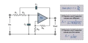
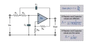
A standard Sallen-Key second-order low-pass uses two resistors (R1 and R2), two capacitors (C1 and C2) and one op-amp. The two RC networks, R1-C1 and R2-C2, set the frequency response. The op-amp runs in a non-inverting configuration, and its gain and feedback network control the quality factor (Q) and the overall shape of the response.
Q, damping and what the response looks like
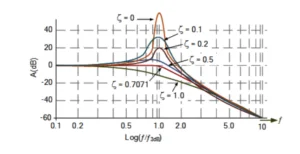
Q describes how much resonance or peaking sits near the cutoff (natural) frequency. A higher Q gives a more pronounced peak; a lower Q gives a more damped response. The damping factor is tied to Q by ζ = 1 / (2Q), where ζ is the damping factor and Q is the quality factor.
The damping state falls into three regions. Overdamped responses are strongly damped with no resonant peak. Critically damped sits at the boundary between the two. Underdamped responses can show overshoot or a resonant peak. A second-order Butterworth response has Q ≈ 0.707 and ζ ≈ 0.707, which lands in the flat, no-peaking region.
The amplitude response follows the same logic. At low Q the rolloff is gradual and free of significant peaking. As Q rises, a peak develops near the cutoff. The Butterworth case gives a maximally flat passband with its −3 dB point at the specified cutoff frequency.
Here's the thing: the amount of gain and feedback you pick isn't a free parameter. It sets Q, and it also affects stability. Push Q up by raising the gain, and you're moving closer to the edge where the stage can oscillate.
Worked example: 159 Hz low-pass with Q = 5
Take a non-inverting second-order low-pass with R1 = R2, C1 = C2, Q = 5 and a cutoff frequency of 159 Hz.
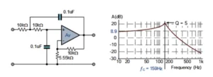
Step 1: Set the capacitor. With equal components, fc = 1 / (2πRC). Choosing R = 10 kΩ and rearranging gives C = 1 / (2π × 159 × 10000), which works out to about 0.1 µF. So R1 = R2 = 10 kΩ and C1 = C2 = 0.1 µF.
Step 2: Set the gain. With equal R and C values in a unity-gain Sallen-Key low-pass, Q comes out to 0.5. Getting to a higher Q means adjusting the op-amp gain. For the equal-component non-inverting configuration, Q = 1 / (3 − A), where A is the non-inverting voltage gain. Rearranged, A = 3 − (1 / Q). For Q = 5, A = 3 − 0.2 = 2.8.
The non-inverting gain follows A = 1 + (Rf / Rg), so the feedback resistor ratio should be chosen to give a gain of about 2.8.
Note: A Q of 5 gives significant resonance near the natural frequency. This is not a Butterworth response. It demands careful attention to stability and component tolerances, because a small shift in the gain setting moves Q noticeably.
Second-order high-pass
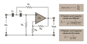
The high-pass version passes high frequencies and attenuates low ones. Its circuit is similar to the low-pass, with the positions of the resistors and capacitors swapped, and the same frequency-scaling and design principles apply. It also shares the same roll-off figure of about 40 dB per decade (12 dB per octave) in the stopband below cutoff. Above cutoff, the feedback network sets the voltage gain, which you can choose to suit the application.
Where these filters earn their place
Second-order sections show up in audio systems, where they separate frequency ranges; in communication systems, where they strip out unwanted components; and in signal processing and sensor circuits, where they reduce noise. In data acquisition, a second-order stage ahead of an analog-to-digital converter limits frequencies that would otherwise alias into the band of interest. Electronic control systems use them to improve signal quality.
The trade-off is that you give up some flexibility to keep the design simple. You get a steeper roll-off than first-order stages, you can build with commonly available parts, and you can cascade stages for higher order. What you have to manage is the Q-versus-stability relationship, and that's where most of the design time goes.