Transformer Windings: Copper vs Aluminium, Winding Types and Monitoring Tools
- Published
- Author
- Komal Ganvir
- Reads
- 787
How winding materials and layouts are chosen, and how resistance meters and winding temperature indicators help keep transformers in service.
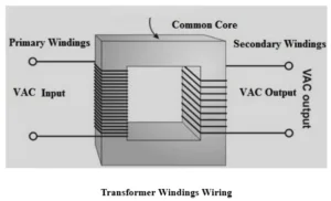
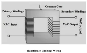
The winding is where a transformer does its real work. Several turns of insulated conductor wrapped around the core carry energy from one circuit to another through electromagnetic induction, and every design decision about the winding traces back to the input and output requirements, mainly voltage and current ratings. The primary winding receives energy from the supply, and the secondary winding delivers it to the load. Get the winding wrong and nothing else in the transformer matters much.
Copper or aluminium: the material trade-off
Almost every transformer winding is either copper or aluminium, and the choice comes down to a trade between conductivity, weight and cost. Copper offers high electrical conductivity and good mechanical strength, which is why it dominates power and distribution transformers. Aluminium is lighter and generally cheaper, but its higher resistivity means you need a larger conductor cross-section to reach similar electrical performance. That extra copper-equivalent bulk is the penalty you pay for the savings, and it shows up in the physical size and insulation layout of the finished unit.
Here's the thing: aluminium's cost advantage is real only if the designer accounts for the larger conductor. Compare the two on material price alone and you'll miss the dimensional and cooling consequences.
Winding types and where each one fits
Winding construction is classified by voltage rating, current capacity and application, and the eight families below cover most of what you'll encounter. The chart image in the source illustrates the layouts.
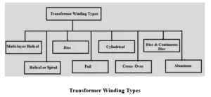
Multi-layer helical windings are used in high-voltage units, particularly those rated 110 kV and above. Several cylindrical layers connect in sequence, and the outer layers may be shortened relative to the inner ones to shape the capacitance distribution. That shaping helps the winding respond better to surge conditions.
Helical or spiral windings suit low-voltage, high-capacity designs with high current and few turns. They are commonly found in units rated roughly 160 to 1000 kVA with voltages between 0.23 and 15 kV. Because the conductor is built from multiple parallel strips, current spreads across them. Three variants exist. Single helical windings use one layer of turns in a screw-like path along the axis. Double helical windings use parallel conductors in a double-helix arrangement, which the source notes helps reduce circulating and eddy-current losses. Disc-helical windings place conductor strips side by side in a radial pattern.
Disc windings are built by connecting several discs in series, each one a set of turns of insulated conductor. Spacers between discs maintain separation and leave room for cooling oil. They are mechanically strong and common in high-voltage work, and the construction gives designers flexibility in how conductors and insulation are arranged.
Foil windings use thin copper or aluminium sheets wound in a spiral, either as a single foil or several in parallel. They suit high-current, large-capacity units, and they keep current distributed across the conductor width while staying compact.
Cylindrical windings appear mainly in low-voltage transformers, built from round or rectangular conductors wound in cylindrical layers. Vertical spacers between layers can form oil ducts that improve cooling. They are a staple of distribution transformers where a simple, sturdy arrangement is the priority.
Cross-over windings are generally used in small transformers. Dividing the winding into several coils reduces the voltage difference between adjacent layers, and insulating material between coils lowers insulation stress and adds mechanical strength.
Disc and continuous disc windings appear in large-capacity transformers. Flat coils connect in series or parallel to match the electrical design, usually from rectangular strips wound radially. Pressboard spacers and barriers separate the sections, and oil ducts between them support cooling. The main strength here is resistance to axial forces.
Aluminium windings are widely used in dry-type and low-voltage transformers. The lower initial material cost and light weight drive the choice, and aluminium is comparatively easy to shape. The higher resistivity again calls for a larger cross-section, and the final performance depends on the design, conductor dimensions, insulation and cooling arrangement together.
Measuring winding resistance
A winding resistance meter is a diagnostic instrument for measuring the electrical resistance of windings, and it tells you about the health of conductors, joints and connections. Measurements are normally taken between the appropriate terminals or phases and compared against expected values or earlier test results. A reading that drifts from the baseline can point to loose connections, poor contacts, damaged connections or shorted turns.
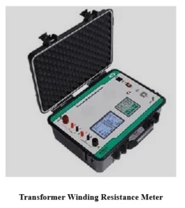
The same class of instrument is used well beyond transformers. The source lists generator and motor windings, inductors, tap changers, power cables and busbar connections. The meters are built for highly inductive equipment, including high-voltage power transformers, where inductance makes a simple resistance reading slower to settle. Tap changer contacts are a common case, since a high-resistance contact there often shows up in this test before anything else.
Keeping winding temperature in check
Winding temperature rises with load because electrical losses increase. To keep operation within safe limits, transformers are monitored with temperature indicators, and two instruments are standard. The winding temperature indicator (WTI) gives an estimated or measured winding temperature. The oil temperature indicator (OTI) tracks the temperature of the transformer oil.
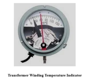
A WTI monitors the high-voltage and low-voltage windings and can connect to alarm, trip and cooling-control circuits. Traditional pointer-type indicators show two readings at once: the current winding temperature and the maximum recorded during operation. Alarm and trip set points can be configured, and when the winding reaches a preset limit, the indicator activates the matching control or protection function. That link to cooling control means the WTI does more than report; it can start fans or pumps before a problem develops.
Where windings earn their keep, and where they cost you
Well-designed windings give good electromagnetic coupling between primary and secondary, can deliver high mechanical strength with suitable conductor and insulation choices, and can be sized for a wide range of voltage, current and power ratings. Winding design also affects losses, and reliability depends on proper manufacture and maintenance.
The downsides are practical. Winding work needs skilled labour and specialised equipment, and poor placement affects both electrical performance and insulation. Materials and insulation processes push up production cost. Faults such as shorted turns or loose connections degrade performance, and high winding temperatures shorten insulation life when cooling falls short. Most of these failure modes are exactly what the resistance meter and temperature indicators are there to catch.
Where windings show up
Windings sit at the heart of power distribution, where distribution transformers bring energy to suitable voltage levels. They also make voltage transformation possible in step-up and step-down units, and they provide electrical isolation between two circuits in isolation transformers. Power transformers at generating stations and substations handle transmission duty, while smaller units supply power supplies, chargers and other electronic equipment. Industrial transformers feeding machinery round out the picture.
What to take from it
The winding sets the transformer's electrical character, and the choices of conductor material, winding type and cooling layout all follow from voltage, current and capacity requirements. My read is that the monitoring side matters as much as the construction. A resistance reading that drifts from its baseline or a winding temperature that creeps toward its alarm setting usually gives you warning well before a failure. Designing the winding right and watching it closely are two halves of the same job.