Co-Packaged Optics in a 3 kW AI Package Requires Liquid Cooling
- Published
- Author
- Vladimir Stojanovic
- Reads
- 692
A joint simulation found air cooling missed temperature limits, while an impingement cold plate met targets for a package exceeding 3 kW.
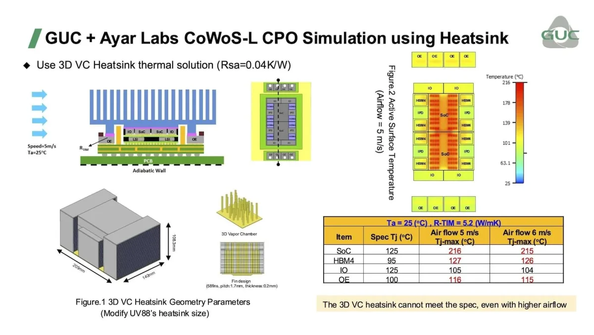
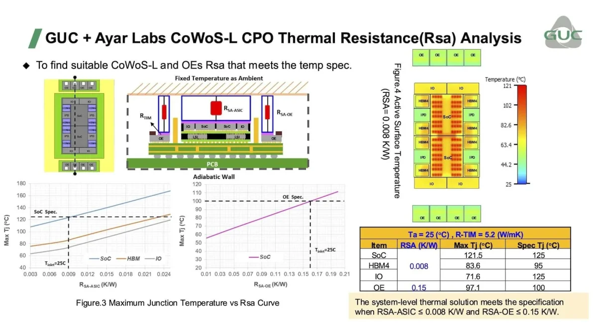
For this co-packaged optics (CPO) design, liquid cooling is the difference between meeting chip temperature limits and exceeding them. Ayar Labs and Global Unichip Corp. (GUC) simulated a multi-chip package drawing more than 3 kW and found that a standard air fin heatsink failed the thermal targets, while an impingement cold plate kept every component within specification.
The result speaks to a practical constraint on putting optical links beside high-power AI processors: the optical engines have to share a dense package with chips that generate substantial heat. The companies’ analysis maps the thermal interactions and identifies cooling targets for a specific package design. Its power assumptions were static, so dynamic workload behavior remains to be evaluated.
A large package with optical links
The proposed XPU multi-chip package integrates Ayar Labs’ TeraPHY optical engines into GUC’s advanced packaging and ASIC workflow. The optical engines attach directly to the organic package substrate, replacing traditional electrical interconnects with a full-duplex optical interface rated above 100 Tbps from the XPU package. The source describes this as more than an order of magnitude above current XPUs.
Within the package, UCIe-S carries bandwidth between the optical engines and I/O chiplets over the substrate. UCIe-A connects each I/O chiplet to the main AI die through local silicon interconnect (LSI) bridges. The 105 mm × 140 mm package contains two XPUs, each 25.69 mm × 32.40 mm; eight HBM4 modules; four I/O chiplets; and eight TeraPHY optical engines, each 12.5 mm × 13.0 mm.
The design uses a 9-2-9 layer substrate for routing. Its mechanical design includes a stiffener that accounts for optical-engine requirements and supports detachable fiber connections while addressing mechanical stress and package warpage. Thermal optimization takes place at the XPU package level, alongside signal and power integrity work.
Modeling heat across chiplets
GUC’s thermal integrity flow combines chip power maps with thermal crosstalk and dynamic thermal co-simulation. The purpose is to identify local hotspots and estimate how heat from neighboring dies and the wider package affects optical-engine temperatures, from early design through sign-off.
For this study, the companies intentionally examined a demanding customer package form factor to probe thermal stability. Heat generated across the package can influence optical performance, so the analysis treats the optical engines as part of the same thermal system as the processors, memory, and I/O dies.
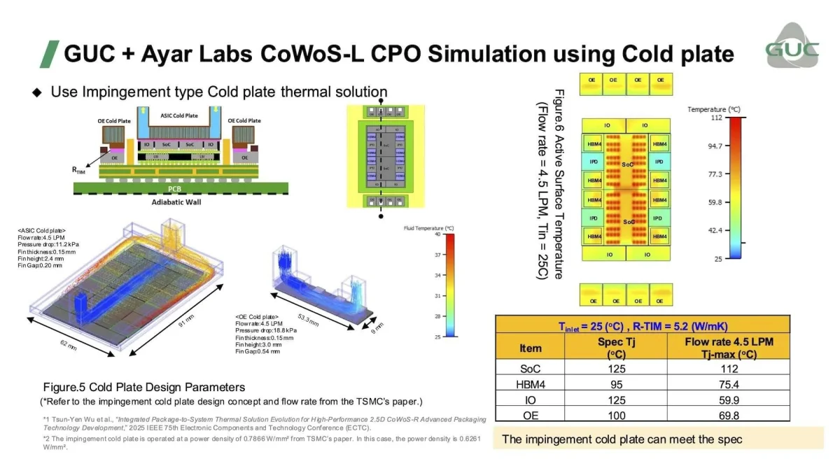
Three analyses were performed: a thermal resistance assessment to establish component targets, an air-cooled heatsink simulation, and a liquid-cooled cold plate simulation. The heatsink case used air at 25°C and speeds of 5 m/s and 6 m/s. It missed specification for every component except the I/O die, with temperatures significantly above limits.
Cold plate meets the modeled targets
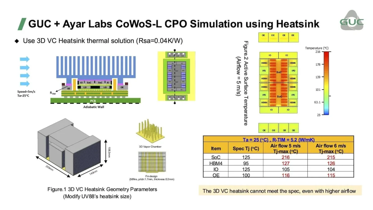
The resistance analysis set system-level targets of RSA-ASIC ≤ 0.008 K/W and RSA-OE ≤ 0.15 K/W for the ASIC and optical engine. The cold plate design reached those values, with pressure drops of 11.2 kPa for the ASIC plate and 18.8 kPa for the optical-engine plate. The separate cold plate simulation used an impingement design at 4.5 LPM, and all components remained below their temperature specifications.
Impingement cooling was selected because it can remove higher heat flux than conventional parallel-channel designs. The modeled fin dimensions were 0.15 mm thick and 2.4 mm high for the ASIC, and 0.15 mm thick and 3.0 mm high for the optical engine. The thermal interface material conductivity was K=5.2 W/mK.
For thermal sign-off, the stated limits were HBM4 below 95°C, SoC below 125°C, and optical engines below 100°C. The study also mapped hotspot locations. The package’s total power envelope exceeds 3 kW, including 1,500 W from the AI processors alone. The companies report that the simulated liquid solution met the stated temperature targets under these conditions.
Static power leaves a key question
The findings show that this package’s cooling choice has direct consequences for CPO integration: the tested air heatsink did not meet the limits, while the modeled cold plate did. They do not yet describe changing power over time. The simulations used constant power assumptions, whereas real systems ramp from idle and fluctuate during boot, training, and normal demand.
Ayar Labs and GUC plan to study dynamic workloads next, including how the optics respond to temperature changes and heat spikes. That work will help determine whether the thermal margins seen under static assumptions hold as workloads vary. For now, the clearest engineering takeaway is that CPO can fit within this high-power package’s thermal envelope when the cooling system is designed to meet the identified resistance targets.